computer aided cost analysis
One of the current tendencies for companies which offer rapid prototyping services is to be equipped with numerous prototyping technologies so as to satisfy the wide range of customer needs. The various layer manufacturing technologies differ not only in the material used but also in the operating principle and the modalities by which the material is layered on each single slice of the prototype. The computer aided methods for cost prediction can be dedicated to specific technologies or based on a parametric approach. The first approach requires that a lot of information, dealing with the kinematics and dynamical performances of the machine, should be known. For this reason, considering that companies operating in the RP sector are equipped with numerous prototype technologies, this approach cannot be used to implement general purpose software that automatically elaborates the model without a skilled operator. Parametric models are of general purpose, relatively simple to implement, but their effectiveness depends on the choice of the driving cost factors. The cost of an object made with rapid prototyping depends on a number of factors, some of which are easy to determine, while some others are more closely linked to the prototyping technology used.
DRI.F.E. Version 2 Release 1
DRI.F.E. 2.1 estimates some factors, specifically oriented to parametric cost analysis of rapid prototypes, by computing the 3D geometric model provided in STL format (ASCII or Binary).
DRI.F.E. 2.1 provides to warn defects of the STL input file and automatically repair some of them.
The parameters estimated by DRI.F.E. 2.1 are summarised in the following table in which their importance for some typical Layer Manufacturing technologies are evidenced.
FDM SLA SLS LOM MJM 3DP EBM SLM
MATERIAL
Volume
yes yes yes yes yes yes yes yes External Area
yes yes yes yes yes yes yes yes Total layer's contour
yes yes yes yes no
no
yes yes N# of repositionings
yes yes yes no
yes yes yes yes Prototype height
yes yes yes yes yes yes yes yes Projected area on the plane X-Y
yes yes yes yes yes yes yes yes
SUPPORT
Volume
yes yes no
yes yes yes no
no
Total layer's contour yes yes no
no
no
no
no
no
N# of repositionings yes yes no
yes yes yes no
no
Support height yes yes no
yes yes yes no
no
In the following the input technological parameters are reported:
- Hatch model distance;
- Layer model thickness;
- Hatching model vector;
- Hatch support distance;
- Layer support thickness;
- Hatching support vector;
- Base support thickness.
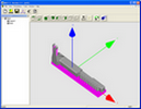
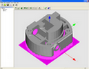
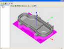
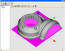
In the following figures screenshots (click to enlarge) of the software are reported.
Details of the algorithm used in DRI.F.E. 2.1are reported in:

 Di Angelo L., Di Stefano P., "Parametric cost analysis for web based
e-commerce of layer manufactured objects", International Journal of
Production Research, Volume 48 (7), 2010, pp. 2127 - 2140, ISSN:
0020-7543..
 Di Angelo L., Di Stefano P., "A neural network based build time
estimator for layer manufactured objects". International Journal of
Advanced Manufacturing Technology, vol. 57 (1), 2011, p. 215-224,
ISSN: 1433-3015.
Di Angelo L., Di Stefano P., "A neural network based build time
estimator for layer manufactured objects". International Journal of
Advanced Manufacturing Technology, vol. 57 (1), 2011, p. 215-224,
ISSN: 1433-3015.- Di Angelo L., Di Stefano P., " Build time estimator for layer manufactured object". In Proceedings of the 6th International Conference on Intelligent Processing and Manufacturing of Materials (IPMM), June 25 - 29 2007, Salerno, Italy.


